


Train Power - When DC is not Direct Current
Half-Wave Ripple plus ~7V DC to make 11V RMS
This is the second (or third if you count the previous diversion into history) in a continuing series of posts on powering model trains. The first installment covered some basics of DC motor design, and if you haven’t read it, it’s worth at least a skim before reading today’s post, since it provides a lot of background information (or read the DC Train Motors page, which has been updated considerably from the original material). Today we’ll get into how modern “DC” power packs aren’t really DC, and what aspects of DC motor behavior make that a good thing.
As before, I’m describing the “permanent magnet brushed DC motor” typical of most modern HO and N scale models. There are other kinds of motors, which may have differences (brushless, coreless and AC motors have all been used for model trains), but these are the most common kind.
Today’s post took a lot longer to write than I’d anticipated; it turned out to be an even more complex topic than I’d thought, and I wanted to cover all the bases. Perhaps I should have broken it up into several posts. At that, I have more material I will cover another day.
DC that isn’t DC
Most modern “DC” power packs don’t really put out DC in the sense of a fixed voltage for a given throttle position. The reason for this is that DC motors don’t really run very well at slow speeds. They work best at a fairly high rotational speed. In the early days hobbyists had to be content with models that went from “stop” to “rather quick” with no intermediate speed. This is often referred to as a “jack rabbit start”, and it’s hardly prototypical. Real locomotives weigh several hundred tons. Nothing that heavy accelerates quickly, and if it’s pulling a train that can weigh upwards of 10,000 tons it’s even slower to get up to speed.
Passenger trains (multiple unit type) tend to weigh less, and often have more and distributed power so they can accelerate faster. But there are limits to that, as passengers tend to object to being hurled backwards. And “weigh less” still means that a train will weigh 100 tons or more without passengers, and a full load of those can easily add 50 tons. That’s a lot to accelerate quickly.
I’ll get into the details below, but the short version is that modelers discovered that “pulsing”, or varying the power in a repeating manner, allowed a train to start more gently. This wasn’t without its problems, and various different approaches were tried over the years, although the earliest technique proved quite effective and continued in use for over twenty-five years. In fact many systems today use a technique known in the 1950s, but not considered “the best” at the time. It’s still a compromise, but a popular one. Today all but entry-level DC power packs produce pulsed power in some form, and it’s so commonplace that most don’t even mention it. There are exceptions, of course.
DCC also uses something akin to pulsed power, although it has significant differences.
Motors and Speed
Let’s look briefly at how an electric motor powers a train.
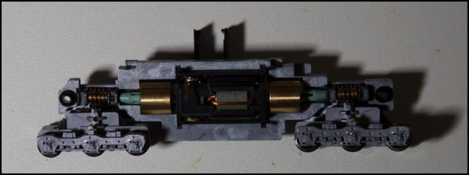
This is a typical N-Scale model (a Kato SD40 to be specific) with half the frame removed to show the motor and drivetrain. As the armature (gray metal in the center of the black motor assembly) turns, the shaft through its center turns, and the two large brass flywheels on the ends of the shaft turn. Connected to the flywheels are two drive shafts (green plastic) that connect to worm gears at each end of the train (brass). All of this is turning at the same speed as the motor’s armature. That speed depends on the “average voltage” going through the armature windings (the reddish copper wires seen wrapped around the armature here).
The truck assembly has a set of gears (one visible at far left above and between two axles, another touching the worm gear; these are black plastic and hard to see) that connect to the axles and reach up to the worm gear above them. As the worm gear turns, the gears turn the wheels. Because several gears of different size are used, there’s a “gear ratio” in effect here: for each turn of the motor a wheel only makes a partial turn. This is expressed as a ratio, such as 12:1, meaning 12 motor turns are required for one turn of a wheel.
For modern N-scale diesels (and it doesn’t vary much for larger scales), 12:1 is fairly common. For steam locomotives, ratios can be much higher, 30:1 or even 40:1, because the driving wheels were are larger in diameter. Passenger locomotive will have smaller ratios than freight locomotives, to allow higher top speed at a sacrifice in pulling power (torque).
The exact ratio would, or should, be chosen to relate the normal running speed of the motor at “full” voltage to the desired top scale speed of the model, which would vary significantly from a switch engine to a road freight or a passenger train, although in practice I don’t think many manufacturers bother with that. In either case, the motor is turning at full rotational speed (or a large fraction of it) at full throttle, but much more slowly if you are doing low-speed switching of cars in a yard or something similar (perhaps only 3% of top speed).
Taking a specific example: I have a model with a motor that makes 14,000 RPM at 12 volts, and has a 12:1 gear ratio to wheels that are 5.55 mm in diameter across the tread (just under 1/4”). At top speed the wheels are turning at just under 1,200 rpm, causing the model to move 339 mm/s (about 13.3 inches/second), a scale speed of 195 kph (121 mph) in 1:160 N-scale. That’s a bit fast for a freight, although the model will run slower pulling a train. At that speed each winding is changing polarity roughly every 2.1 milliseconds (twice per cycle, 14000/60 cycles per second). A full cycle (one rotation of the motor) takes 4.2 milliseconds. If I want to run the model at 5 kph (3 mph), the motor needs to turn at about 2.6% of top speed, or just 360 rpm.
Electromagnetic FIelds
In a motor of this type, the magnetic field created in the armature by the current flowing through the windings is what accomplishes the task of converting electrical current into mechanical work, by pushing against the constant magnetic field of the permanent magnets. This magnetic field needs to be reversed every half cycle, so in effect it’s created and torn down twice per rotation.
In an ideal frictionless motor with no load, electricity would only need to flow until the magnetic field was created, at which point the motor would be turning and no more power would be required until it was necessary to reverse the field a half-turn later. In a real motor, there is always a load (friction) and a motor doing any useful work has an additional load (mechanical resistance to the turning of the shaft, due to the drag of the cars being pulled). A continued supply of electricity is needed to provide the energy to do that work (pulling the load, overcoming friction).
As with any flowing electricity, some if it gets lost as heat in the resistance of the wires wrapping the armature. The more load, the more electricity, and the more heat from such loss. That resistive loss is an important aspect of motor operation, which we’ll come back to later. This source of heat doesn’t actually depend on the speed of the motor or the voltage applied to it, but on the amount of work the motor is doing, because that’s what causes the current to increase (higher voltage allows the motor to do more work, and draw more current if needed, but it doesn’t force it to).
And eventually the motor has made a half turn, and now the magnetic field in the armature needs to be reversed to keep the motor turning. To do that, the old one must be torn down before the new one can be created.
When it is torn down, the energy used to create it has to go somewhere, and part of it (the “hysteresis loss”) goes into the armature as heat. That’s a normal part of DC motor operation as well, and motors are designed to lose a small amount of energy this way. Motors are actually very efficient at converting electrical power to mechanical power when run at their rated speed on DC, with efficiencies approaching 90%, so very little is wasted as heat in either resistive or hysteresis loss in the normal (non-model-railroad) case.
Note: there are other sources of loss, but they’re either very small (eddy current heating loss) or not affected by pulsing or load (mechanical friction loss), so I won’t talk further about them here.
If you use pulses, and the gap between pulses is long enough, the field will die down partway through a rotation and need to be recreated. And each time you cycle through adding and removing the field, the “hysteresis loss” occurs, producing more heat. How quickly does this happen? Very quickly indeed. The interesting number here is the motor’s inductive “time constant”, or the inductance divided by the resistance. For the example given above, that number is 86 microseconds, and in just 5 “time constants” the field will fully decay, so this loss takes less than half a millisecond for full effect. If the field doesn’t die all the way down, some energy is still lost, just not all of it.
Note: motors also have a “mechanical time constant”, which depends on the physical design of the motor. This can cause certain kinds of pulsed power to be bad due to excessive vibration, and it also has an effect on power use. However, the necessary physical characteristics required to derive this value aren’t documented for the motors we use, so we have to count on motor designers to have chosen a “good” one; we can’t verify it with any methods I’m aware of.
For pulses occurring at the typical scale for wall power (8 or 16 milliseconds for 60 Hz, 10 or 20 milliseconds for 50 Hz), the magnetic field needs to be fully recreated for each pulse at low speeds, and this has an effect.
It’s worth mentioning that every N-scale motor I’ve tested, from several Japanese and non-Japanese manufacturers, had electrical time constants around 85 - 125 microseconds, so this conclusion likely holds true for all N-scale motors. I’ve only tested a couple of HO motors, and they had longer time constants, but not a lot longer: the longest was 364 microseconds for a typical inexpensive Chinese-made can motor in a Walthers model. That one would take 2 milliseconds to fully die down, so even with pulses every 8 milliseconds, the behavior is effectively the same as for N-scale.
Speed And Pulses
Now lets suppose we want to run the model at a scale 5 kph (3.1 mph), a reasonable low speed for switching purposes. Despite the limitations that might prevent a model from working well at that speed, I have managed that with some of my models out-of-the-box, so it is a reasonable goal. I’ll call this the “switching” speed.
At that speed, the motor is turning at about 358 RPM (let’s round that to 360), or 6 revolutions per second. Each winding is thus reversing polarity 12 times a second, or every 83 milliseconds. A full rotation takes 166 milliseconds.
Let’s also consider a slightly faster speed, appropriate for low-speed running in a yard, of 25 kph (15.5 mph), roughly what railroads refer to as “restricted” speed. At that speed, motor RPM is about 1,800, and the windings are changing polarity every 33 milliseconds. A full rotation takes 66 milliseconds.
Motors don’t work well at low speeds. They tend to want to stop due to irregular torque produced over the rotational cycle, a characteristic of the motor geometry. The exact speed where this ceases to be a significant factor depends on the design of the motor. But for the sake of discussion, let’s assume that problems are likely to occur from zero up to somewhere between switching speed and restricted speed, but not at higher speeds. That’s somewhat close to reality for a typical model.
A very typical solution to this is to “pulse” the power. At “restricted speed” a pulse every 8 milliseconds (the duration of half an AC wave) will repeat after roughly 1/8 of a rotation. That means that there will be four pulses before the armature polarity reverses. That’s long enough to ensure the winding is getting a good amount of power, although because the time between pulses is 8 milliseconds, the magnetic field will need to be re-established for each pulse, so four times as much power will be wasted doing that as would be lost with constant-voltage DC that only had one hysteresis cycle per half rotation.
At switching speed, when we need the most benefit of the pulses, an 8 millisecond pulse lasts just one twentieth of a rotation, so there will be ten pulses, an even better result as far as keeping power in the armature. However, again we’re losing energy as heat with each pulse, and now we’re losing it ten times as much as with a DC motor.
At very high speed, the pulse lasts over several armature reversals (which happen every 2.1 milliseconds as described above). This is actually good, because it means that at higher speed when heating may be more of a concern we’re not wasting power in multiple pulses per half-rotation with this kind of pulsed power.
If we switch the pulsing cycle to 16 milliseconds (which we get from half-wave rectified power) now there are only 5 pulses per half-rotation at switching speed, and just two at restricted speed. We’re getting less work out of the motor since the coil is effectively unused half the time, although that can be compensated for by turning up the pulse amplitude to increase the average voltage over the interval. There’s another problem that comes out of this however.
The following chart shows how full and half-wave power works (at full throttle). The power from the transformer, which would peak at 20 volts for a 12V track voltage, is being rectified to put the pulses on the positive side. This also reduced the voltage slightly, 1.1V lost to rectification is typical. A full-wave ripple is just this rectified output without any filtering, and it has an average (not RMS) voltage of 12.0 volts. Meters tend to read in RMS, but motors care about the average.
Before people started pulsing power, a capacitor would be added to the output of the rectifier, and with a big enough capacitor, what you’d get would be 12V DC with no variation at all. This could be fed into a rheostat (variable resistor) to reduce the voltage as the operator turned the throttle knob, to bring a train from full speed (at 12V) down to stopped (at around 3V or less). After “pulsed power” was discovered people started taking the filter capacitors off their power supplies. More on that below.
A power supply that produces half-wave ripple merely turns off half the rectifier. My old MRC ThrottlePack 501 has a switch for this, as did many other power supplies dating from the 1960’s and 1970’s, before people realized that half-wave ripple wasn’t such a good idea. In the early days (c. 1960) it was considered the best form of pulsed power.
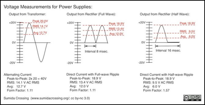
Note: form-factor seems to have more than one definition. The above numbers appeared in several sources. I saw others listing full-wave as 1.4 and half-wave as 1.9. I think the difference may be the form-factor of the voltage versus that of the current (and current is what matters), but nobody writing on this is really very clear about that.
A Bit of Motor History
The first electric motors were Direct Current (DC) motors, because back then the only source of power were chemical batteries. In fact one of the first that could do useful work, Davenport’s motor of 1834, was a brushed DC motor (using stator coils, not permanent magnets). In 1835 he demonstrated it using a model train. The first electric-powered model railroad thus dates back nearly to the introduction of real trains in America, although the route was just a simple circle and the “train” wasn’t a model of a real train.
In truth, credit for the first useful electric motor probably belongs to the Prussian Moritz Jacobi, who demonstrated his in 1834, so it was likely invented slightly earlier than Davenport’s. Jacobi neglected to use a train in his demonstration however, so I’ll stick with Davenport. If nothing else, he was the first to apply a DC electric motor to a model train.
There were other motors before Davenport and Jacobi, so the definition of “first” depends on how you qualify it. None of the earlier ones were considered more than demonstrations of electromagnetism, rather than machines to do work, although clearly people were thinking in that direction. The electric motor was really a development that was obvious based on earlier work, and likely independently invented (in the sense of making a machine from a known principle) by many different people at about the same time.
These early motors were run off chemical batteries (Volta cells), which produced DC at a constant voltage. Those were weak and expensive, so these motors didn’t get used much at first. Later, Alternating Current (AC) motors tended to be used for industrial purposes since it was easier to distribute AC over a distance, but DC motors were also used, and gradually became more common for low-voltage uses.
Electric motors were first used in model trains (other than Davenport’s) in the 1890’s. These became increasingly preferred to wind-up models and by 1910 electric model trains were the norm. Many of the early ones were AC, but by the 1920’s that was changing.
DC Motors and Model Trains
Brushed DC permanent-magnet motors were in use by model railroaders by the 1920s, and became more commonplace as the hobby developed in the 1930’s.
In the U.S., according to this history, Mantua (later to be known as Tyco) first advertised their six-volt model 100 motor in a hobbyist magazine in 1930. While they also made AC motors, by January 1935 Model Railroader could note that “most” modelers in the then-new HO scale were using DC motors. The majority of these early motors, although not all, were permanent-magnet motors, and initially 6V was the standard voltage, because car batteries were a convenient power source (they could be recharged if you owned a car or lived near a garage), and at the time car batteries were 6V batteries.
While some O-scale motors were already using 12 volts (two batteries in sequence), HO didn’t convert until 1946, when it once again became possible to buy model-size motors (wartime regulations had prohibited the use of critical supplies for purposes deemed non-essential, like hobbies). Not only were 12 volt motors suddenly everywhere, conversion kits were being sold, and some stores were providing credits if you turned in your old 6V motor when buying a new one. Additionally the higher-power Alnico magnets (available to hobbyists from the late 1930’s) were in use, and the combination of higher voltage and stronger magnets made for much more powerful motors pulling trains.
The 1930s also saw the development of rectifiers for converting household AC into DC, likely related to the rise of residential electrification (in the U.S. anyway) in that decade. At first hobbyists tried to recreate the characteristics of the batteries they had been using by “filtering” the output of rectifiers, to remove any trace of variable voltage from the DC output. This was still common practice after the war.
After 1946, motor technology was relatively static until inexpensive “can” motors started to come into use in the 1960s. These motors were originally designed to power other things and used for trains simply due to cost. They used ferrite magnets, which had become a usable technology, although one with less power than the Alnico magnets previously used. On the plus side, it was very hard to demagnetize a ferrite magnet, and unfortunately rather easy to demagnetize an Alnico one. But aside from power, which could be addressed in other ways, the performance characteristics weren’t markedly different from the earlier open-frame Alnico motors, and their advent didn’t affect throttle design.
At some point in here, HO motors started to use voltages higher than 12 volts, and eventually the NMRA standard was updated to remove the specific voltage. When DCC standards were published, HO was shown as having a “typical” motor voltage of about 14.5 volts. This didn’t really change throttle design either (the commercial ones had probably been using higher voltages since the 1960’s; I have at least one example in my MRC 501, a late-60’s design, of one that was).
But motors, and particularly DC motors, work best at relatively high speeds. Try to make one run very slowly, and it didn’t work as well. Gears could be used to effectively slow the output without slowing the motor, but there was still the problem that the range from “slow but works well” to “maximum speed” was somewhat limited.
It’s not clear when someone realized that pulsing the DC would prove beneficial at low speeds, but it was a known principal before being “discovered” by model railroad hobbyists.
Problems at Low Speed
Several problems affect a motor at low rotational speeds. These include cogging and the difference between static and dynamic friction.
Cogging, the variation in torque produced by the motor at various points in a rotation, is due to the variable attraction between the poles on the armature and the permanent magnet(s) on the frame. It can be addressed by motor designs: both skewed windings and more poles will reduce it.
There is a lot of friction in a model train, even before you connect any cars to the locomotive. The motor shaft turns on bearings, and the brushes rub against the commutator. Gears in the drivetrain rub on each other and on their bearings (which are often plastic on plastic and far from frictionless), and the wheels themselves turn in axle bearings. Very few of these bearings are particularly sophisticated, often they are just metal rubbing on metal (better than plastic on plastic perhaps, but not by much).
One basic principle is that for all normal materials and conditions (there are some exceptions), the amount of force required to start something moving (to overcome static friction) is greater than the amount of force required to keep it moving once it starts (to overcome dynamic friction). In a motor this means that the voltage needed to start it is higher than the voltage needed to keep it in motion, so the speed at starting voltage will be higher than its lowest possible speed. This obviously makes it impossible to smoothly start a motor at the lowest speed.
Cogging can’t be entirely eliminated, and this means that at very low speed, the motor may be prone to stop at certain points in its rotation once voltage drops below a certain minimum, because the torque drops below that needed to move the load (mechanical load: the drag produced by the train due to wheel friction and similar). This can make low-speed running erratic if you turn the voltage down for a train in motion.
There’s something in common to both of these: low voltage, which produces a low magnetic field, which creates a low rotational force (torque). If voltage is higher, they’re all less of a problem. But if voltage is higher, speed is higher.
The key to low speed operation is realizing that it is “average” voltage that sets the speed, but that “peak” voltage can be used to overcome friction and reduce the effect of cogging. With normal DC, peak and average are the same. But if you “pulse” the DC, you can have a peak higher than the average.
Pulsed Power for Model Trains
Pulsed power, at least for model railroading, was discovered in 1953 by Moyes J. Murphy. Like many inventors he’d been working on something else: a “rotary commutator” power supply for his HO trains (essentially a “chopper”, similar to that used in prototype electric trains). This interrupted the power to the motor 90 times a second (one pulse every 11 milliseconds), and to his surprise, the trains ran better at low speeds than on conventional filtered DC. Model Railroader published an article on it in February 1954, What is Pulsed Power? by Linn Westcott, and followed up with a Clinic column in the August 1954 issue answering reader questions about the new technology.
The following diagram shows what Murphy’s rotary commutator was doing (as I understand it from the description; details weren’t published). If this looks a lot like the PWM power from a DCC decoder, that’s because they’re essentially the same: square-wave pulses of varying duration. Pulses like this were in use long before digital circuitry and power transistors made them an attractive solution, although they aren’t the only kind of interrupted-voltage control.
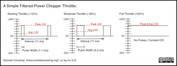
It was quickly determined (by Westcott, working with Murphy) that what mattered was the pulsing, and not how the pulses were generated or their shape, and as a result early throttles using simple half-wave rectification (sixty half-sine pulses per second) became popular, rather than something more complex producing square pulses as in Murphy’s original design. Ironically, they were wrong and it did matter, but it took a while for that to be figured out.
Motor heating was a problem with pulsed systems, and hobbyists were warned to use an ammeter and keep motor current below 70% of the “normal current rating” of the motor. It was later discovered that this kind of pulsing also caused increased wear in the brushes, but I’ll come back to that below.
Simple Pulses: Full and Half-Wave Ripple
The use of full-wave ripple produces a pulse every 8 milliseconds. Ripple throttles adjusted voltage by lowering the peak voltage, using the typical rheostat (variable resistor) throttle control. So a train at full speed would have peaks of 18.9 Volts (12 V average) and a train at half speed would have peaks of 9.4 Volts (6 Volts average). At least in the early days, half-wave ripple was preferred because it had a higher peak voltage relative to the average (see the Voltage Measurements diagram further up the page).
As mentioned, heating of the motor was a problem, particularly at higher throttle settings. Early hobbyists learned not to turn the throttle up all the way on “pulsed” power, but the problem then was that switching from pulse (half-wave ripple) to what was considered non-pulsed (full-wave ripple), as I can do on my MRC 501 by throwing a switch, will cause the average voltage to immediately double, and the train to lurch ahead.
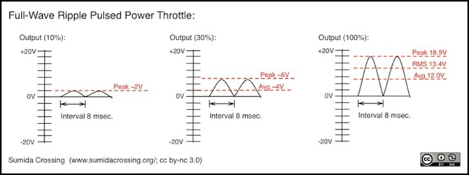
Full-wave ripple is also pulsed power, and while the benefits aren’t as pronounced as half-wave ripple, they do exist. For that reason it is still used today in many power packs (my Kato packs, for example), and it turns out that its ratio of RMS to average (the Form Factor) is often cited by motor manufacturers as the maximum limit of pulsing that should be used, to avoid unnecessary heating and brush wear. That was something it took a while for people to learn.
Half-wave is a different matter. Its form factor is higher than that of full wave. A half-wave throttle will output just 6 Volts average voltage (corresponding to the train moving at half speed) when the pulses are peaking at 18.9 Volts. That shouldn’t be a surprise: we’ve effectively thrown away half the wave, so we’ve thrown away half the voltage. Although the RMS voltage of a half wave is lower than for a full wave, the ratio of RMS to average is still significantly higher, and that causes problems for the motor.
Despite these problems, half-wave ripple hung around for a long time. I have an MRC power pack bought c. 1992 that uses half-wave ripple, although only at lower settings; it uses a rising DC level (like Westcott’s system we’ll get to next) to adjust to non-pulsed power at higher throttle settings.
Westcott’s Square Pulses
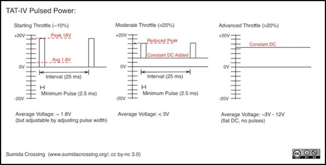
Westcott would later change his mind, and in his March 1969 article on the TAT-IV throttle, Improved Transistor Throttle, he noted that his experience over the previous several years suggested that rather than ripple, the ideal pulse (for his models anyway) was a full-voltage square wave of not less than 2.5 milliseconds duration repeating every 25 milliseconds at minimum throttle, but with it replaced with constant DC at higher throttle settings.
Unlike modern PWM or Murphy’s method, the pulse width was fixed (although it could be changed to vary the “starting voltage”, Westcott’s version of what I’m calling “switching speed”, to be higher or lower). As the throttle was advanced, a constant level of DC was added and the pulse, which remained 2.5 msec wide, shrunk in amplitude until it faded away (at about 3V average power). After that, the throttle was outputting pure DC, which minimized problems from heating.
But why those specific intervals? He didn’t say. Westcott was modeling in HO scale I believe, at a time when HO was using five-pole (and sometimes seven-pole) open-frame motors. One of the standard motors of the day was the Pittman DC-71, which is still sold today by Bowser in an updated form (I bought one to play with, see my Typical Motors page for details). The motor had a reputation for quality and long-term reliability. According to one set of stats the original had a no-load speed of 13,600 RPM (drawing 180 mA at 12 Volts), so it wasn’t very different from a modern motor.
The typical gear ratio of the day for a freight steam locomotive was 30:1, and for a model with 79” driving wheels this means that the motor would be turning at about 640 RPM for the switching speed described above. Passenger and diesel locomotives would run their motors slightly faster for the same speed, so the steam freight locomotive defined the worst-case situation, and is thus a good choice for examining the performance of the throttle.
Note: I’m using a specific example of a freight locomotive for the above, a USRA Pacific, although the driving wheel size was based on a model mentioned in a magazine article, and isn’t quite correct for the prototype.
A speed of 640 RPM means that a rotation was taking 93 milliseconds per rotation, and the armature windings were reversing every 47 or so milliseconds. At double that speed a half-rotation would be roughly equivalent to Westcott’s interval. Faster and some half-rotations would not receive any pulses, but by then the loss of torque that implied would be less of an issue.
Thus Westcott’s interval was probably chosen to ensure that the winding received at least one pulse in any model of reasonable gearing even at moderately low speeds, but not more than two. This would ensure that the motor was getting maximum benefit out of the pulses, with no half-cycles left unpowered. It also means that a relatively low amount of energy would be wasted as heat since the number of pulses per half-cycle were minimized. Since Westcott was aware of the heating problem with early half-wave pulse throttles, this likely also influenced his choice of interval.
I can’t find anything special about the 2.5 msec minimum length. That seems considerably longer than would be needed to avoid inductance-related inefficiencies. It may simply be that less than 1.8 volts (10% of the 18v peak used in his throttle) wasn’t enough to operate a motor. Motors lose a certain amount of voltage in the brushes (anywhere from 0.4V to 2.4V depending on material and other factors), and some minimum amount of voltage above that is required to create enough of a torque to overcome static friction.
The SCR Throttle
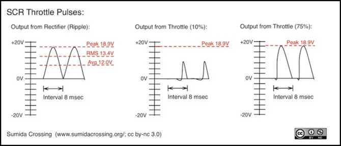
The SCR, a type of diode, was available in the 1960’s and mentioned in a manner implying that some hobbyists had experimented with them for throttles, although I haven’t seen any published designs from that era. It became popular for throttles in the 1970’s, perhaps because of improvements in function or cost. A decade later, their cousin “thyristors” would be running real trains in a similar manner. An SCR is effectively a switch that can be turned on but not off. Used with an AC wave (or full-wave ripple) it will turn itself off when the voltage goes to zero every 8 milliseconds.
SCRs could be used in a throttle by turning on the ripple pulse at different times. Turn on early, and you get nearly all of the sine wave. Turn on halfway, and voltage shoots up to maximum, then declines to zero normally, and you get an average voltage of 50% of the normal average of the sine wave (please excuse the poor curve shapes; my drawing program doesn’t handle curves with a mix of sharp and soft angles very well).
The pulse interval with an SCR would still be 8 or 16 milliseconds (or 10 or 20 for 50 Hz power supplies) unless some non-line source of ripple were used (but using ripple was typical of at least some SCR throttle designs; it was simpler). But unlike adjustable-voltage ripple, the pulse was always of full amplitude (although at less than 50% power it was really the trailing part of the ripple, so the maximum voltage would be less than full).
The problem with SCR throttles, which were quite popular for a time, is that because they’re cutting up the sine wave, the form factor is actually pretty bad. Worse, in fact, than half-wave ripple for some throttle settings.
They were and still are a common technology for electronic speed control of industrial motors however, and motors designed to be more robust (“SCR rated”) were developed. Among other things these had oversized brushes so they didn’t wear as quickly from the stresses involved, and easy-to-replace brushes to simplify maintenance. These, in fact, are the kind of DC motors used with thyristor control systems in full-size trains using DC motors. SCR throttles have, however, fallen out of favor with model railroaders, at least as far as I can tell.
Why a High Form-Factor is Bad
The “Form Factor” is a representation of the abruptness of current change in a motor due to the shape of the changing voltage over time: the higher the form factor, the more abrupt the change. In straight DC, there is no change, and the form factor is 1.0. The more abruptly the change happens, the higher the form factor (we’ll come back to PWM in the next section, as it can be an exception).
When voltage is applied abruptly, the current doesn’t respond immediately because the motor windings function as an inductor, and inductors resist changes in current. Instead the voltage causes the current to ramp up over time to the level that would normally be set by the motor’s resistance (the stall current, as it turns out). As the current increases, the magnetic field increases, and the motor turns faster. And as the motor turns faster, the Back-EMF increases and tends to balance out the applied voltage (less whatever amount of voltage is needed to do work). This is why a lightly loaded train zipping down the track uses far less current that the “still current”.
Once things settle down, the voltage difference (source voltage less Back-EMF) is only enough to produce the current needed to balance the load. But at the start of the pulse, the difference is greater. And the faster the pulse ramps up from zero, the greater that initial difference.
The problem with large form factors is that they represent a rapid spike to a relatively high voltage. That voltage will try to make a current flow, but it can’t at first. This causes a voltage difference between the applied voltage and the voltage related to the current in the windings. And this is created where the brushes touch the commutator, because the inductor is on the commutator side of that connection. Put simply, it causes a voltage difference across the brush-to-commutator gap that can be very large, for a short time.
High enough voltage, and small amounts of air will become conductive. As the shaft turns, small air-gaps are created between the edges of the brushes and the edges of sections of commutator rotating towards or away from them. Arcs form across those gaps, eroding both the brushes and the commutator pads themselves and producing heat in the brushes and commutator/shaft assembly. The arcing also produces radio noise.
All brushed DC motors have some amount of arcing at full and near-full voltage, but a high form factor means that there’s more of it and at lower applied voltages. And while modern motors may be designed to be driven by control systems that uses pulses (like PWM) so they have brushes that are oversized compared to what would be needed for simple DC to limit this problem, it’s still not good for it to happen.
Why Square Waves are Bad, Sort Of
Square waves are close to the worst thing you can do with electricity in a motor. They produce the largest difference between applied voltage and flowing current. You might wonder then why PWM (which is nothing but square waves) is often described as having a very good form factor, typically only 5% above perfect DC (form factor of 1.05). The problem lies in the assumptions behind the number, which are rarely stated, and there are two very critical ones.
First, most people writing about the behavior of motors assume they’re running at close to their design speed, meaning very quickly. That’s because motors run otherwise aren’t very efficient, and so the usual solution is to run the motor fast except for a very brief time when starting and stopping, and use gears if the shaft needs to turn more slowly. At high speed, the PWM pulses occupy most of the interval, and so PWM becomes very close to full voltage DC.
Model trains don’t work that way, because the models need to operate over a wide range of speeds, and it’s not practical to put a gear-shift in the model to change gear ratios for different speeds. So sometimes the motor is turning at design speed, but often it’s turning slower, sometimes much slower (as slow as 3% of design speed).
The second is that most people writing about PWM assume you’re using PWM with a frequency of many kilohertz, because that’s how modern PWM controllers for larger motors are designed. If the frequency is high enough that the magnetic field doesn’t have time to die down between pulses, then the current will likewise remain relatively constant, and again PWM is acting like DC.
At low pulse frequencies (a couple of kHz or below) and slow rotational speeds (short pulses), the magnetic field can fully die down between PWM pulses. The form factor of this is not anywhere close to the one usually cited for PWM. That doesn’t mean PWM with low frequencies can’t be used, it just means that there will be energy lost as heat if it is. Much of that heat (from hysteresis loss) winds up in the motor. And, unfortunately for the model trains, DCC had, and to some extent still has, good reason not to use high-frequency PWM.
DCC had the awkward problem of trying to fit a PWM motor controller into a very tiny space, with a limited ability to dissipate heat from the circuit (the inside of a closed plastic model isn’t be best place to cool electronics). And the faster you switch transistors, the more energy you lose in them as heat. This led to early PWM controllers being low frequency. You’d get more heat out of the motor, but less out of the circuitry. That’s less of an issue today, twenty years on from those early DCC decoder circuits, but it’s still something of an issue.
A second consideration is that low-frequency DCC acts like pulsed power, while high-frequency PWM acts like DC. As we’ve seen, pulsed power is advantageous for low-speed operation of DC motors, so even though low-frequency PWM isn’t ideal from a motor-heating or efficiency perspective, there has been a willingness to tolerate those problems to gain the operational benefits.
And while low-frequency PWM will contribute more motor heating, and slow-turning motors don’t cool themselves as well, in practice unless the motor is heavily loaded (e.g., crawling up a grade with a long freight train) it’s not producing much resistive heating, so there’s margin for excess hysteresis heating from low-frequency PWM pulses. And at high speeds, the motor is changing field polarities quickly as the armature rotates, roughly every 1 - 2.1 milliseconds for typical motors. Pulses that last longer than this aren’t contributing much extra to heat in that situation, even if they’re widely-spaced due to a low frequency.
But still, this is why supersonic PWM is a good method of driving a motor if you can use other methods to handle low-speed operation: it minimizes heating loss by ensuring that the gap between even the shortest pulses is long enough to reduce or prevent energy loss.
DCC isn’t the only non-supersonic PWM out there. The 500 Hz PWM produced by an Arduino (by default; it can be adjusted) is producing roughly one pulse per rotation at full speed, but more at lower speeds, and its pulses are fairly short (0.15 milliseconds at 30% throttle), so it’s going to be contributing a fair amount of heat at all but the highest speeds. It’s useful if you need high torque (it’s effectively pulsed power), but again a pretty bad form of electricity to inflict on a motor.
Getting back to older forms of square waves: Murphy’s original chopper circuit used 1.1 millisecond pulses at the lowest throttle, and longer ones as the throttle advanced. This was enough to avoid problems. Similarly Westcott’s 2.5 millisecond pulses were long enough to largely avoid the problem. There were extra pulses per cycle some of the time, but not many, and so there was little additional hysteresis loss than was going to occur from the half-rotation winding reversal anyway.
How Much Heat Is There, Anyway?
Since I’m a curious sort, I set up a locomotive with the motor exposed (no plastic body shell) on my test track and ran it with various types of power, at various speeds, to see how warm it became. I couldn’t test Murphy’s or Westcott’s throttles since I don’t have examples of either.
But I do have a number of other interesting power sources I can test. These include straight DC, a DC+ripple method somewhat similar to Westcott’s, both full and half-wave ripple, and a more complex modern system (the MRC 780 I reviewed last month). I also have DCC, which can run at both low and high frequencies, which can be tested by connecting the PWM output of the decoder to the track, so the locomotive isn’t modified. And I have an Arduino (several actually) and know how to run it at different PWM frequencies.
Since I it’s going to take some time to do all of that testing, and I would like to post at least once during the month of February, I’m going to tease you with one set of measurements, and promise the next in a future post (which I really do intend to get out next week, but I might write about something else if the testing takes longer).
Testing was performed with my Atlas B23 on a loop of level track with the locomotive alone, so resistive heating due to load-based current would be minimized, letting the loco run in circles until the armature temperature stabilized and checking it while the loco was in motion, using an IR thermometer. Room temperature was 23.5°C (that’s about 74°F, but I’m going to just report results in C today, since that’s how I measured them and I’m feeling lazy). I let the motor cool down in between tests of different power supplies.
The armature temperature was recorded using an IR thermometer with a min/max function, held to one side of the moving loco and trying to track it along a short section of the test track I could easily reach. This provided a second or so for the thermometer to get a good reading, but it was very approximate due to aim and distance, and most readings varied by two or even three degrees C each time around the track. So the results I’m reporting approximate the middle of the range, to the nearest half-degree, over a half-dozen or more readings for each source and voltage.
The temperatures actually stabilized in a minute or two, and perhaps even faster. It doesn’t take the motor long to react to a change.
My first tests were with a regulated and filtered 12V bench supply. My oscilloscope confirmed that this was producing very flat DC indeed (no visible ripple at all). I needed to turn it up to 6V to get a meaningful test, as the loco tended to stall at lower voltages (one section of my test track has some issues with connectivity). I tested at 6.00, 8.00, 9.00, 12.00 and 14.97V (the latter the highest the supply would go). Current draw reported by the supply was 0.11A at 8V, 0.11 - 0.12A at 9V, 0.12 - 0.13A at 12V and 0.13A at 15V. So what I’m basically seeing is the current staying fairly constant (since the load is relatively light and doesn’t vary much as the voltage changes), which is what I’d expect. This means that resistive heating is going to stay relatively constant as well (it’s related to load), so minor variations in voltage between tests, and even not so minor ones, won’t change the heating due to resistive losses.
Thus any observed heating is almost certainly due largely to hysteresis loss based on the shape of the pulse (some will be due to friction at higher speeds).
Temperature in the DC test tracked the current for the most part, staying between 31 - 33°C at all speeds (my accuracy in measurement doesn’t get much better than that, unfortunately). At 6.0V the scope was reporting 6.1V RMS (I suspect the scope is more accurate), and the train was making a circuit of the test track in a leisurely 33.5 seconds. At 12.0V on the power supply, the scope was reporting 12.1 - 12.2V RMS (likely due to the noise being generated by the motor, the voltage was not quite flat by 12 volts). And the train was moving briskly, taking 7.75 seconds to complete one loop of the track.
My next test was with one of my Kato power packs, putting out full-wave unfiltered ripple. I couldn’t measure current for this. At the lowest setting, the scope was reporting 6.1V RMS, the train was making a loop in 32.5 seconds, and the temperature was about 34°C (again varying about a degree either way). So the ripple was producing perhaps 2 degrees more heating to move the train at almost exactly the same speed as the DC. At 12.2V RMS (per the scope), a loop of the track took 8.25 seconds, and temperature was around 35°C, so there was some rise in temperature for higher speed, but not a lot.
Finally, I ran two tests with my old MRC 501 power pack. This can’t handle low speed very well, so I set up the first test to mirror the 12V Kato test as best I could, just to show that the two were similar. To do that, I had the MRC set to about 30% throttle, which was about as low as I can put the throttle on it before it stalls (rheostat throttles don’t work too well for modern trains). A track cycle took 8.13 seconds, and temperature was around 33.5°C, so it was slightly slower and cooler than the Kato. The scope also reported peak voltage (ignoring noise) of around 16 Volts.
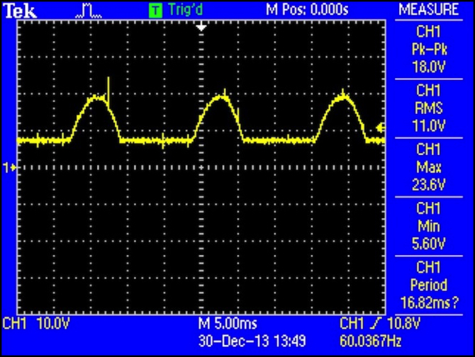
The final test was to switch the MRC to “Pulsed” power (half-wave ripple), and set the throttle to produce the same peak voltage (16V) as in the full-wave test. The scope trace at the top of the page is for an older test of this pack doing basically the same thing, so it’s close to what I saw on the scope during this test.
The scope reported 8.5V RMS for this, which might actually be accurate. Time around the track was 19.32 seconds, so it was on a par with the Kato pack at 8 Volts. However the temperature for this test was averaging around 39°C.
So for a motor that runs about 8.5°C above ambient on DC with no load, and 9.5°C - 11.5°C above ambient using full-wave ripple, the use of half-wave ripple makes it run 15.5°C above ambient at the same peak voltage (and a much lower average one). Is 5°C enough to be damaging? It’s unlikely to damage the motor outright. And I don’t know how much extra heat there would be with a load (I have some tests planned for that), nor do I know what amount is “safe” for this motor. So I can’t really say.
Note: while 39°C (102°F) is rather warm in absolute terms, styrene plastic doesn’t easily deform until temperatures exceed 75°C (170°F), so it’s not close to a temperature that would harm the model.
But it’s certainly confirmation that pulsed power does cause heating, and that pulses with higher form factors cause substantial heating even at low average voltage. Which isn’t really a surprise, as people had figured this out in the 1960’s. But I always like to see things with my own eyes.